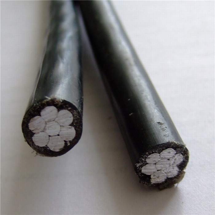
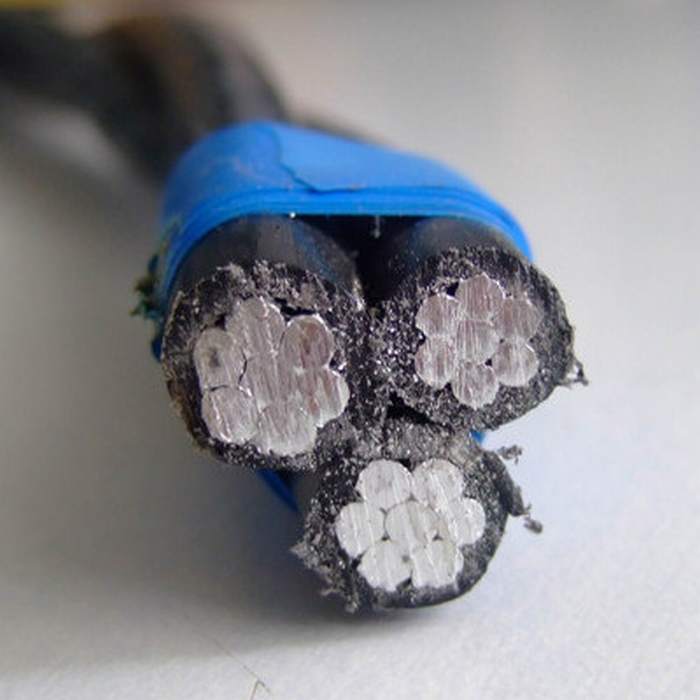
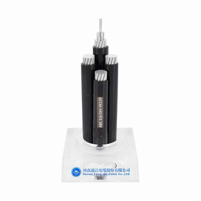
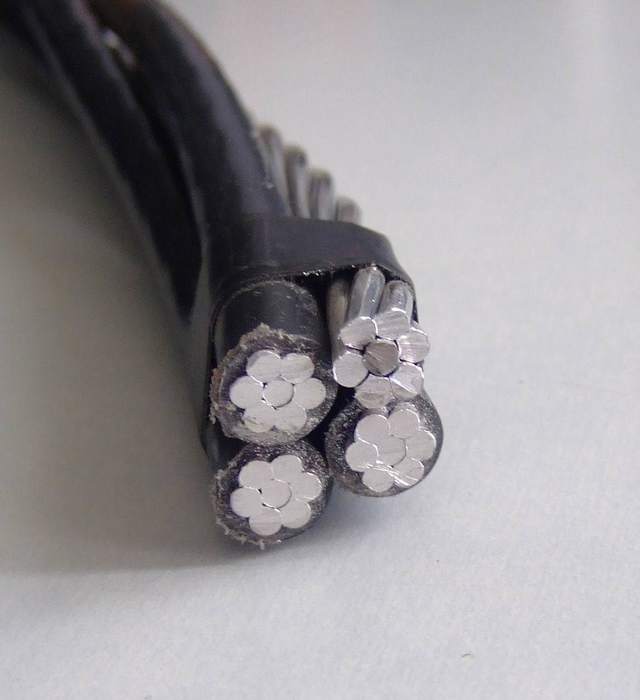
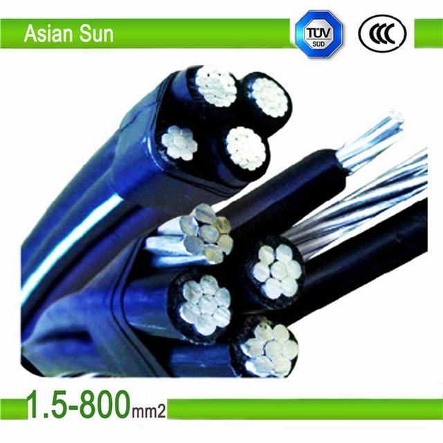
Cavo in Dotazione per antenna/alluminio/ABC/AAC/AAAC/ACSR
Informazioni di Base
Sotterraneo
CE ,
CCC ,
RoHS
Informazioni Aggiuntive.
Descrizione del prodotto
Product Description
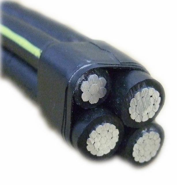
ABC Cable; Service Drop Cable
The basic construction is as follows:
3 power cores consisting of standard aluminium conductors, insulated withXLPE insulation
+ One sheath lighting aluminium conductor with XLPE insulation(optional)
+ One messenger Al-alloy conductor (bare or covered)
The messenger conductor can be of galvanised steel wire also.
The purpose of messenger wire is
A) It acts as load bearing wire.
B) It acts as earth or neutral conductor.
To be used at cotages of 600V phase-to-phase or less and at conductor temperatures not to exceed 75oC for polyethylene insulated conductors or 90oC for crossliked polyethylene(XLPE) insulated conductors.
It meets or exceeds the following specifications:
1. Aluminum Wire, 1350-H19 for Electrical Purposes.
2. Aluminum Conductors, Concentric-Lay-Stranded.
3. Aluminum Conductor, Concentric-Lay-Stranded, Coated Steel Reinforced(ACSR)
4. Concentric-Lay-Stranded 6201-T81 Conductors
5. Compressed Round Stranded Aluminum Conductors Using Single Input Wire.
It meets or exceeds all applicable requirements of ANSI/ICEA S-76-474
Applications:
To supply 120 volt aerial service for temporary service at construction sites, outdoor or street lighting. For service at 600 volts or lower at a conductor temperature of 75C maximum.
Construction:
Concentric strand or compressed 1350-H19 conductor, polyethylene or crosslinked polyethylene insulation, concentric strand AAC, ACSR, or 6201 alloy neutral messenger.
Standards:
1. B-230 Aluminum Wire, 1350-H19 for Electrical Purposes.
2. B-231 Aluminum Conductors, Concentric-Lay-Stranded.
3. B-232 Aluminum Conductors, Concentric-Lay-Stranded, Coated Steel Reinforced (ACSR).
4. B-399 Concentric-Lay_Stranded 6201-T81 Aluminum Alloy Conductors.
5. B498 Zinc-Coated Steel Core Wire for Aluminum Conductors, Steel Reinforced (ACSR).
6. Duplex Service Drop cable meets or exceeds all applicable requirements of ANSI/ICEA S-76-474
0.6/1KV AAC/AAAC/ACSR XLPE/PE Insulation ABC cable AAAC conductor has been widely used in power transmission lines and electricity distribution lines with various voltage levels, because they have such good characteristics as simple structure, convenient installation and maintenance, low cost large transmission capacity. And they are also suitable for laying across rivers valleys and the places where special geographical features exist.
2. Standard
We can produce as per the standard of GB, IEC, ASTM,DIN,CSA,JIS and also particularly customize and manufacture according to your special requirement.
Standards / Testing Specifications
IEC 61089, BS 3242, DIN 48201, ASTM B399, BS EN50183, GB/T 1179-2008
Working conditions aerial insulation power cable
1) Rated voltage: 0.6kV/1Kv
2) The tallest working temperature of the cable conductor; XLPE insulation cable: 90°C;
HDPE insulation cable: 75°C;
3) During having a short (lasting less than 5 seconds) the maximum temperature;
XLPE insulated cables is 250°C;
HDPE insulated cable is 150°C
4) During the cable lying, the ambient temperature must be above-20°C
5) Bending radius allowance of the cable;
A)1Kv aerial insulation power cable:
It should be no less than 4D for the cable with outer diameter less than 25mm;
It should be no less than 6D for the cable with outer diameter of 25mm or more;
B) 10kV aerial insulation power cable:
Single core cable: 20 (D+d)±5%mm;
Multi-core cable:15 (D+d)±%mm
Formula inside: D-Actual cable outer diameter;
d-Actual conductor outer diameterl
Standard Packaging
As provided by standards and customer’s requirement.
| BS7884-1997 | |||||
| Nominal Area | Stranding | Diameter of conductor | Linear mass | Rated strength | D.C. resistance at 20°C |
| mm2 | No./mm | mm | Kg/km | KN | Ω/km |
| 10 | 7/1.35 | 4.05 | 89.82 | 3.752 | 1.829 |
| 14 | 7/1.6 | 4.8 | 126.2 | 5.627 | 1.30300 |
| 16 | 3/2.65 | 5.72 | 148.30 | 6.194 | 1.10600 |
| 16 | 7/1.7 | 5.10 | 142.40 | 5.946 | 1.15400 |
| 25 | 7/2.1 | 6.30 | 217.30 | 9.073 | 0.75630 |
| 32 | 3/3.75 | 8.10 | 296.90 | 12.4 | 0.55200 |
| 32 | 7/2.46 | 7.38 | 298.20 | 12.442 | 0.54970 |
| 35 | 7/2.5 | 7.50 | 308.00 | 12.86 | 0.53370 |
| 50 | 7/3.00 | 9.00 | 443.50 | 18.52 | 0.37060 |
| 50 | 19/1.8 | 9.00 | 435.80 | 17.7 | 0.38190 |
| 70 | 7/3.55 | 10.65 | 621.10 | 25.93 | 0.26460 |
| 70 | 19/2.1 | 10.50 | 593.20 | 24.09 | 0.28060 |
| 95 | 19/2.5 | 12.50 | 840.70 | 34.14 | 0.19800 |
| 100.0 | 7/4.3 | 12.90 | 911.20 | 36.54 | 0.18100 |
| 120.0 | 19/2.8 | 14.00 | 1055.00 | 42.83 | 0.15780 |
| 125.0 | 19/2.9 | 14.50 | 1131.00 | 45.94 | 0.14710 |
| 150.0 | 19/3.2 | 16.00 | 1377.00 | 55.94 | 0.12080 |
| 150.0 | 37/2.25 | 15375.00 | 1334.00 | 53.88 | 0.12640 |
| 185.0 | 19/3.55 | 17.75 | 1695.00 | 68.86 | 0.09815 |
| 185.0 | 37/2.5 | 17.75 | 1647.00 | 66.49 | 0.10240 |
| Phase | Phase | Phase | Approx.Overall Diameter | Max. D.C. Resistance of Conductor at 20 Centigrade | |||
| AAC+UV-XLPE | Compact Conductor | UV-XLPE Insulation | |||||
| No.X Normal Cross Section of Cores | No.of Al Wires | Overall Diameter | Normal Thickness | Min. | Diameter | ||
| No. X mm 2 | – | mm | mm | mm | mm | mm | ohm/km |
| 1 X 10 | 7 | 4.05 | 1.0 | 0.8 | 6.05 | 6.05 | 3.08 |
| 1 X 16 | 7 | 4.8 | 1.2 | 0.98 | 7.2 | 7.20 | 1.91 |
| 1 X 25 | 7 | 6 | 1.2 | 0.98 | 8.4 | 8.40 | 1.20 |
| 1 X 35 | 7 | 7.0 | 1.4 | 1.16 | 9.8 | 9.80 | 0.868 |
| 1 X 50 | 7 | 8.3 | 1.4 | 1.16 | 11.1 | 11.10 | 0.641 |
| 1 X 70 | 19 | 9.8 | 1.4 | 1.16 | 12.6 | 12.60 | 0.443 |
| 1 X 95 | 19 | 11.6 | 1.6 | 1.34 | 14.8 | 14.80 | 0.320 |
| 1 X 120 | 19 | 13 | 1.6 | 1.34 | 16.2 | 16.20 | 0.253 |
| 1 X 150 | 19 | 14.6 | 1.8 | 1.52 | 18.2 | 18.20 | 0.206 |
| 1 X 185 | 36 | 16.2 | 2.0 | 1.70 | 20.2 | 20.20 | 0.164 |
| 1 X 240 | 36 | 18.4 | 2.2 | 1.88 | 22.8 | 22.80 | 0.125 |
| 2 X 10 | 7 | 4.05 | 1.0 | 0.8 | 6.05 | 12.10 | 3.08 |
| 2 X 16 | 7 | 4.8 | 1.2 | 0.98 | 7.2 | 14.40 | 1.91 |
| 2 X 25 | 7 | 6 | 1.2 | 0.98 | 8.4 | 16.80 | 1.20 |
| 2 X 35 | 7 | 7.0 | 1.4 | 1.16 | 9.8 | 19.60 | 0.868 |
| 2 X 50 | 7 | 8.3 | 1.4 | 1.16 | 11.1 | 22.20 | 0.641 |
| 2 X 70 | 19 | 9.8 | 1.4 | 1.16 | 12.6 | 25.20 | 0.443 |
| 2 X 95 | 19 | 11.6 | 1.6 | 1.34 | 14.8 | 29.60 | 0.320 |
| 2 X 120 | 19 | 13 | 1.6 | 1.34 | 16.2 | 32.40 | 0.253 |
| 2 X 150 | 19 | 14.6 | 1.8 | 1.52 | 18.2 | 36.40 | 0.206 |
| 2 X 185 | 36 | 16.2 | 2.0 | 1.70 | 20.2 | 40.40 | 0.164 |
| 2 X 240 | 36 | 18.4 | 2.2 | 1.88 | 22.8 | 45.60 | 0.125 |
| 3 X 10 | 7 | 4.05 | 1.0 | 0.8 | 6.05 | 13.07 | 3.08 |
| 3 X 16 | 7 | 4.8 | 1.2 | 0.98 | 7.2 | 15.55 | 1.91 |
| 3 X 25 | 7 | 6 | 1.2 | 0.98 | 8.4 | 18.14 | 1.20 |
| 3 X 35 | 7 | 7.0 | 1.4 | 1.16 | 9.8 | 21.17 | 0.868 |
| 3 X 50 | 7 | 8.3 | 1.4 | 1.16 | 11.1 | 23.98 | 0.641 |
| 3 X 70 | 19 | 9.8 | 1.4 | 1.16 | 12.6 | 27.22 | 0.443 |
| 3 X 95 | 19 | 11.6 | 1.6 | 1.34 | 14.8 | 31.97 | 0.320 |
| 3 X 120 | 19 | 13 | 1.6 | 1.34 | 16.2 | 34.99 | 0.253 |
| 3 X 150 | 19 | 14.6 | 1.8 | 1.52 | 18.2 | 39.31 | 0.206 |
| 3 X 185 | 36 | 16.2 | 2.0 | 1.70 | 20.2 | 43.63 | 0.164 |
| 3 X 240 | 36 | 18.4 | 2.2 | 1.88 | 22.8 | 49.25 | 0.125 |
| 4 X 10 | 7 | 4.05 | 1.0 | 0.8 | 6.05 | 14.64 | 3.08 |
| 4 X 16 | 7 | 4.8 | 1.2 | 0.98 | 7.2 | 17.42 | 1.91 |
| 4 X 25 | 7 | 6 | 1.2 | 0.98 | 8.4 | 20.33 | 1.20 |
| 4 X 35 | 7 | 7.0 | 1.4 | 1.16 | 9.8 | 23.72 | 0.868 |
| 4 X 50 | 7 | 8.3 | 1.4 | 1.16 | 11.1 | 26.86 | 0.641 |
| 4 X 70 | 19 | 9.8 | 1.4 | 1.16 | 12.6 | 30.49 | 0.443 |
| 4 X 95 | 19 | 11.6 | 1.6 | 1.34 | 14.8 | 35.82 | 0.320 |
| 4 X 120 | 19 | 13 | 1.6 | 1.34 | 16.2 | 39.20 | 0.253 |
| 4 X 150 | 19 | 14.6 | 1.8 | 1.52 | 18.2 | 44.04 | 0.206 |
| 4 X 185 | 36 | 16.2 | 2.0 | 1.70 | 20.2 | 48.88 | 0.164 |
| 4 X 240 | 36 | 18.4 | 2.2 | 1.88 | 22.8 | 55.18 | 0.125 |
- Next: Aluminum-Alloy Conductors Steel Reinforced Aacsr for Overhead
- Previous: Bare Aluminium Conductor Alloy Reinforced with ASTM Standard


